The Butterfly Valve Mystery
CPM’s recent project with a water utility client captured amazing footage providing a simple explanation for the (considered) inconsistent data captured through the client’s modeling software.

CPM’s recent project with a water utility client captured amazing footage providing a simple explanation for the (considered) inconsistent data captured through the client’s modeling software.

CPM was contracted to perform a condition assessment inspection along two sections of 8-inch ductile iron pipe (DIP) waste activated sludge lines located in Arizona.
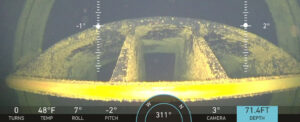
Protecting human divers one Deep Trekker PIVOT inspection at a time. How a subaqueous swimming CCTV inspection solved the unknown in a 48-inch, potable water, intake pipeline 600-feet below.

An Arizona suburb pursues a long-term program to identify and locate leaks across its potable water pipeline system.
How one North Texas city is using new technology to protect its constituents from unforeseen water outages and loss.

Blazing the trail of large diameter pressure pipe rehabilitation in the U.S.